In air piston compressors, the effects of the valve system, which is responsible for taking the air into the cylinder and compressing it, increasing the pressure and pushing it out of the cylinder, on the compressor performance were examined experimentally in this study. It has been determined that the power drawn by piston compressors varies depending on the spring tensions of the suction and discharge valves, and as a result of the experiments, it has been observed that when the spring tensions are reduced, the power drawn by the compressor decreases.
The design parameters of the suction and discharge valves used in piston air compressors directly affect the operation of the compressor. In valve system, the suction side is responsible for taking the air into the cylinder, and the discharge side is responsible for transferring the air out of the cylinder after it is compressed and pressurized in the cylinder.
Piston compressors are generally used to provide the necessary compressed air to pneumatic tools and air-powered equipment. The main elements of a piston compressor are the crankcase, the crankshaft in the crankcase, the connecting rods, the pistons connected to the connecting rods, the piston pins and bearings, the cylinders in which pistons move, the valve systems that allow the air into the cylinders and pressed out, and the cylinder on the valve systems. The locations of these elements are shown in Figure 1.
Figure 1: Reciprocating Compressor Parts
This study was conducted on concentric valves and the valve parts are shown in Figure 2. In concentric valves, air is taken into the cylinder by vacuum effect created by the movement of the piston from Top Dead Center to Bottom Dead Center. The discharge side of the valve is in the closed position during air suction. The absorption of air is completed when the piston reaches Bottom Dead Center, and the air in the cylinder is compressed during its movement from Bottom Dead Center to Top Dead Center. At a certain point in the compression stroke, air is transferred out of the cylinder by opening the discharge side of the closed suction and discharge valves. While the discharge side of the valve is open, the suction side is closed.
Figure 2: Valve Parts
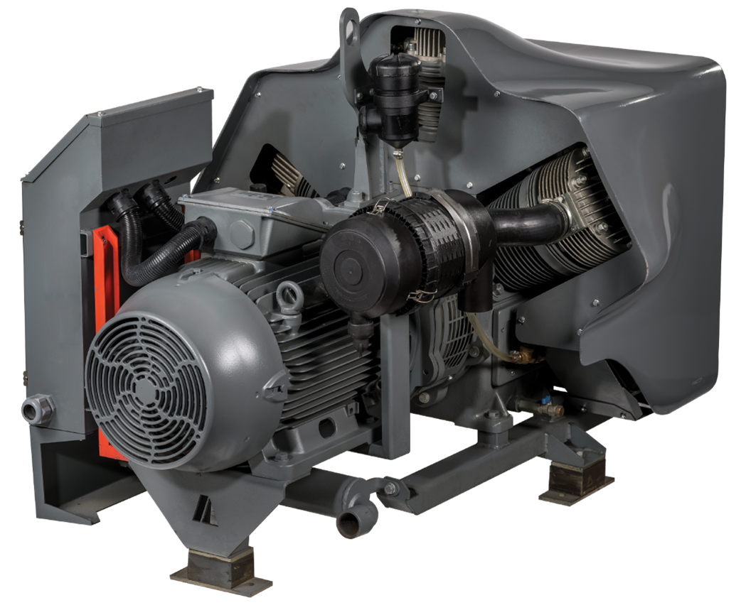
Within the scope of the study, a three-stage 40bar reciprocating compressor used (Figure 3). The compressor, whose air inlet and outlet to the cylinders are provided by a concentric valve system, is driven by a 4P electric motor with a power of 30 kW. In the first stage of the compressor, two compression springs and three suction springs shown in Figure 1 are connected in series. One each of the suction and discharge valves, which open and close according to the direction of air passage, are mounted. By changing the number of springs in the valve, the cylinder internal pressure change and the compressor power change were observed. In order to calculate the power drawn by the compressor, ± 0.05% F.S. was used in the test setup. Torque meter with measurement accuracy of ± 0.1% F.S. a pressure transmitter with measurement sensitivity was used. For in-cylinder pressure measurements, pressure sensors were mounted by opening 5 metric threads near the discharge area of the valve. The pressure transmitters and torquemeter used are shown in Figure 4. The data were recorded on the computer using the data logger and software.

Figure 3: Test Compressor
Figure 4: Pressure Transmitter and Torquemeter
The location where the pressure transmitter is connected is shown in Figure 5.
Figure 5.
As a result of the improvements made in design parameters as a result of the experimental study, the change of the first stage cylinder internal pressure change over time is shown in Graph 1 and Graph 2. Test and mathematical model results regarding the change in the power drawn by the compressor over time are shown in
Graph 1.
Graph 2.
Graph 3.
The average power drawn by the compressor, calculated based on the torque measured by the torque meter connected to the compressor and the crankshaft revolutions, are shown in Table 1.
Table 1.
In this study, the change of cylinder internal pressure and therefore the power absorbed by the compressor with time was compared for different concentric suction and discharge valve spring coefficients used in reciprocating compressors. It has been observed that the power absorbed by the compressor decreases as the spring coefficients decrease. It has been determined that the effect of the change in the spring coefficient of the transmitter valve on the compressor power consumption is greater than that of the receiver part.
By examining Graph 1, where the cylinder internal pressures are compared, and when the results of Test 4 are evaluated together with Test 1, it is seen that reducing the compression spring coefficient by half, the cylinder internal pressure decreases from 3.3 bar to 3.1 bar. In addition, the average power drawn by the machine was reduced from 26.8 kW to 25.8 kW.
The change in cylinder pressure and power consumption over time, measured by reducing the compressor's intake valve spring coefficient to two-thirds of the value in Test 1 in Test 2 and to one-third in Test 3, is plotted in Graph 2. When the results are examined, it is seen that the air pressure increases by decreasing the spring coefficient in the suction stroke of the compressor increases the internal cylinder pressure in the first stage discharge stroke. The cylinder internal pressure increased from 3.1 bar to 3.5 bar by reducing the intake valve spring coefficient to one-third.
Considering all these data, cylinder inner pressure changes depending on the difference in valve spring coefficient during suction and compression. Pressure change also affects compressor power. For these reasons, providing energy efficiency in the compressor becomes possible with suction and discharge valve design changes.